When a Voltmeter Reads Zero Are the Currents Equal?
Voltmeters and Ammeters
Voltmeters and ammeters are used to measure voltage and current, respectively.
Learning Objectives
Compare circuit connection of an ammeter and a voltmeter
Key Takeaways
Key Points
- A voltmeter is an musical instrument used for measuring electrical potential difference betwixt two points in an electrical excursion.
- An ammeter is a measuring device used to mensurate the electric current in a circuit.
- A voltmeter is connected in parallel with a device to mensurate its voltage, while an ammeter is connected in series with a device to measure its electric current.
- At the heart of most analog meters is a galvanometer, an instrument that measures current flow using the movement, or deflection, of a needle. The needle deflection is produced by a magnetic force acting on a electric current-conveying wire.
Central Terms
- shunt resistance: a small resistance R placed in parallel with a galvanometer Yard to produce an ammeter; the larger the current to exist measured, the smaller R must be; nigh of the current flowing through the meter is shunted through R to protect the galvanometer
- galvanometer: An analog measuring device, denoted by G, that measures current flow using a needle deflection caused by a magnetic field force interim upon a current-conveying wire.
Voltmeters and ammeters measure out the voltage and current, respectively, of a circuit. Some meters in automobile dashboards, digital cameras, jail cell phones, and tuner-amplifiers are voltmeters or ammeters.
Voltmeters
A voltmeter is an instrument that measures the divergence in electrical potential between two points in an electrical excursion. An analog voltmeter moves a arrow across a scale in proportion to the circuit's voltage; a digital voltmeter provides a numerical brandish. Whatsoever measurement that can exist converted to voltage can be displayed on a meter that is properly calibrated; such measurements include pressure, temperature, and flow.
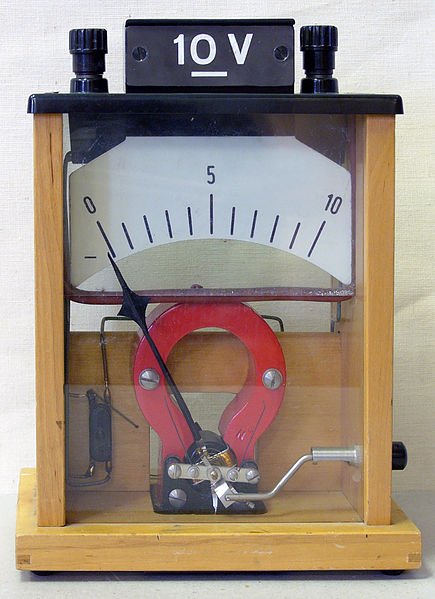
Voltmeter: Sit-in voltmeter from a physics class
In order for a voltmeter to measure a device's voltage, it must be continued in parallel to that device. This is necessary because objects in parallel experience the same potential departure.
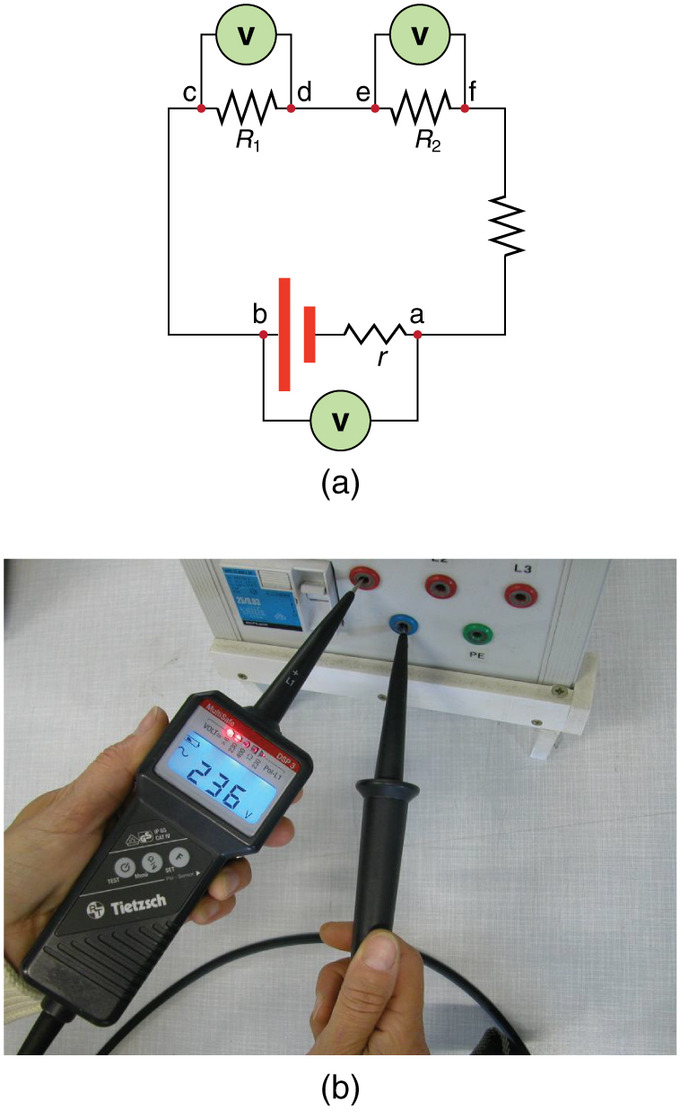
Voltmeter in Parallel: (a) To mensurate the potential difference in this series circuit, the voltmeter (V) is placed in parallel with the voltage source or either of the resistors. Notation that terminal voltage is measured between points a and b. It is non possible to connect the voltmeter directly across the EMF without including its internal resistance, r. (b) A digital voltmeter in use
Ammeters
An ammeter measures the electric current in a circuit. The name is derived from the name for the SI unit for electrical electric current, amperes (A).
In order for an ammeter to mensurate a device'south electric current, it must be continued in series to that device. This is necessary because objects in serial experience the same current. They must not be connected to a voltage source — ammeters are designed to work under a minimal brunt, (which refers to the voltage drop across the ammeter, typically a small fraction of a volt).
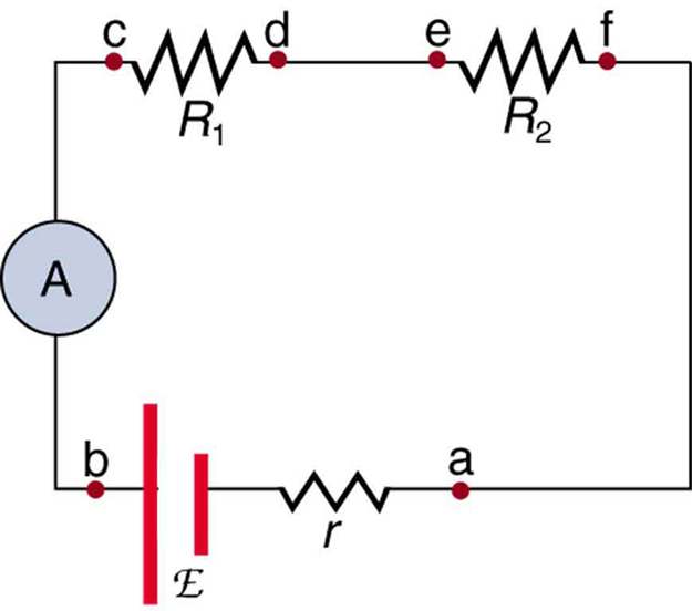
Ammeter in Series: An ammeter (A) is placed in serial to measure current. All of the current in this excursion flows through the meter. The ammeter would take the same reading if located betwixt points d and eastward or between points f and a, as it does in the position shown. (Note that the script capital Eastward stands for EMF, and r stands for the internal resistance of the source of potential difference. )
Galvanometers (Analog Meters)
Analog meters accept needles that swivel to bespeak at numbers on a scale, as opposed to digital meters, which have numerical readouts.The centre of about analog meters is a device called a galvanometer, denoted by Grand. Current catamenia through a galvanometer, IG , produces a proportional move, or deflection, of the needle.
The two crucial characteristics of any galvanometer are its resistance and its current sensitivity. Current sensitivity is the current that gives a full-scale deflection of the galvanometer's needle — in other words, the maximum current that the instrument can measure out. For instance, a galvanometer with a current sensitivity of 50 μA has a maximum deflection of its needle when 50 μA flows through information technology, is at the scale's halfway point when 25 μA flows through information technology, and so on.
If such a galvanometer has a 25-Ω resistance, then a voltage of simply V = IR = (fifty μA)(25 Ω) = ane.25 mV produces a total-scale reading. By connecting resistors to this galvanometer in unlike means, you can utilise it as either a voltmeter or ammeter to mensurate a wide range of voltages or currents.
Galvanometers as Voltmeters
A galvanometer tin function equally a voltmeter when it is connected in series with a large resistance R. The value of R is adamant past the maximum voltage that will be measured. Suppose you desire x Five to produce a full-calibration deflection of a voltmeter containing a 25-Ω galvanometer with a 50-μA sensitivity. Then x V applied to the meter must produce a current of fifty μA. The total resistance must be:
[latex]\text{R}_{\text{tot}} = \text{R} + \text{r} = \frac{\text{Five}}{\text{I}} = \frac{10\text{V}}{50\mu \text{A}} = 200 \text{k}\Omega,[/latex]
or:
[latex]\text{R} = \text{R}_{\text{tot}} - \text{r} = 200 \text{chiliad}\Omega - 25 \Omega \approx 200 \text{chiliad} \Omega.[/latex]
(R is and so big that the galvanometer resistance, r, is nearly negligible. ) Note that v V practical to this voltmeter produces a half-calibration deflection past sending a 25-μA current through the meter, and then the voltmeter's reading is proportional to voltage, as desired. This voltmeter would not exist useful for voltages less than near half a volt, because the meter deflection would be also small to read accurately. For other voltage ranges, other resistances are placed in series with the galvanometer. Many meters allow a selection of scales, which involves switching an appropriate resistance into series with the galvanometer.
Galvanometers every bit Ammeters
The same galvanometer can also function as an ammeter when information technology is placed in parallel with a pocket-size resistance R, frequently called the shunt resistance. Since the shunt resistance is small-scale, well-nigh of the current passes through it, allowing an ammeter to measure currents much greater than those that would produce a total-scale deflection of the galvanometer.
Suppose, for instance, nosotros need an ammeter that gives a full-scale deflection for 1.0 A and that contains the same 25-Ω galvanometer with 50-μA sensitivity. Since R and r are in parallel, the voltage beyond them is the same.
These IR drops are: IR = IGr
so that: [latex]\text{IR} = \frac{\text{I}_\text{1000}}{\text{I}} = \frac{\text{R}}{\text{r}}.[/latex]
Solving for R, and noting that IG is l μA and I is 0.999950 A, we have:
[latex]\text{R} = \text{r} \frac{\text{I}_\text{G}}{\text{I}} = (25 \Omega) \frac{50 \mu \text{A}}{0.999950 \text{A}} = 1.25 \times 10^{-three} \Omega.[/latex]
Null Measurements
Null measurements balance voltages so there is no current flowing through the measuring devices that would interfere with the measurement.
Learning Objectives
Explain why goose egg measurements are employed
Key Takeaways
Key Points
- Measurements of voltages and current with standard voltmeters and ammeters alter the circuit being measured, introducing uncertainties. Voltmeters draw some extra current, whereas ammeters reduce current flow.
- Zip measurements are employed to reduce the doubt in the measured voltage and current.
- The potentiometer and the Wheatstone bridge are ii methods for making null measurements.
- The potentiometer is an instrument that measures an unknown voltage by opposing with a known voltage, without drawing electric current from the voltage source existence measured.
- A Wheatstone bridge is an electrical excursion used to mensurate an unknown electric resistance by balancing two legs of a bridge circuit, one leg of which includes the unknown component.
Primal Terms
- zip measurements: methods of measuring current and voltage more than accurately past balancing the circuit so that no current flows through the measurement device
- potentiometer: an instrument that measures a voltage past opposing it with a precise fraction of a known voltage, and without drawing electric current from the unknown source.
- Wheatstone bridge: An instrument used to measure an unknown electrical resistance by balancing 2 legs of a bridge circuit, one leg of which includes the unknown component.
Null Measurements
Standard measurements of voltage and current alter circuits, introducing numerical uncertainties. Voltmeters draw some extra current, whereas ammeters reduce current catamenia. Null measurements balance voltages, so there is no current flowing through the measuring device and the excursion is unaltered. Null measurements are mostly more accurate but more complex than standard voltmeters and ammeters. Their precision is still limited.
The Potentiometer
When measuring the EMF of a battery and connecting the battery straight to a standard voltmeter, as shown in, the actual quantity measured is the last voltage 5. Voltage is related to the EMF of the battery by V=emf−Ir, where I is the current that flows and r is the internal resistance of the bombardment.

Voltmeter Continued to Bombardment: An analog voltmeter fastened to a battery draws a small merely nonzero electric current and measures a concluding voltage that differs from the EMF of the bombardment. (Notation that the script capital letter East symbolizes electromotive strength, or EMF. ) Since the internal resistance of the battery is not known precisely, information technology is not possible to calculate the EMF precisely.
The EMF could exist accurately calculated if r were known, which is rare. If the current I could be fabricated nix, then 5=emf, and EMF could be directly measured. However, standard voltmeters need a electric current to operate.
A potentiometer is a null measurement device for measuring potentials (voltages). A voltage source is connected to resistor R, passing a constant current through it. There is a steady drop in potential (IR drop) along the wire, then a variable potential is obtained through contact along the wire.
An unknown emfx (represented by script Due eastx) continued in series with a galvanometer is shown in. Note that emf10 opposes the other voltage source. The location of the contact bespeak is adapted until the galvanometer reads nix. When the galvanometer reads goose egg, emfx =IRx , where Rx is the resistance of the wire section upwards to the contact point. Since no electric current flows through the galvanometer, none flows through the unknown EMF, and emf10 is sensed.
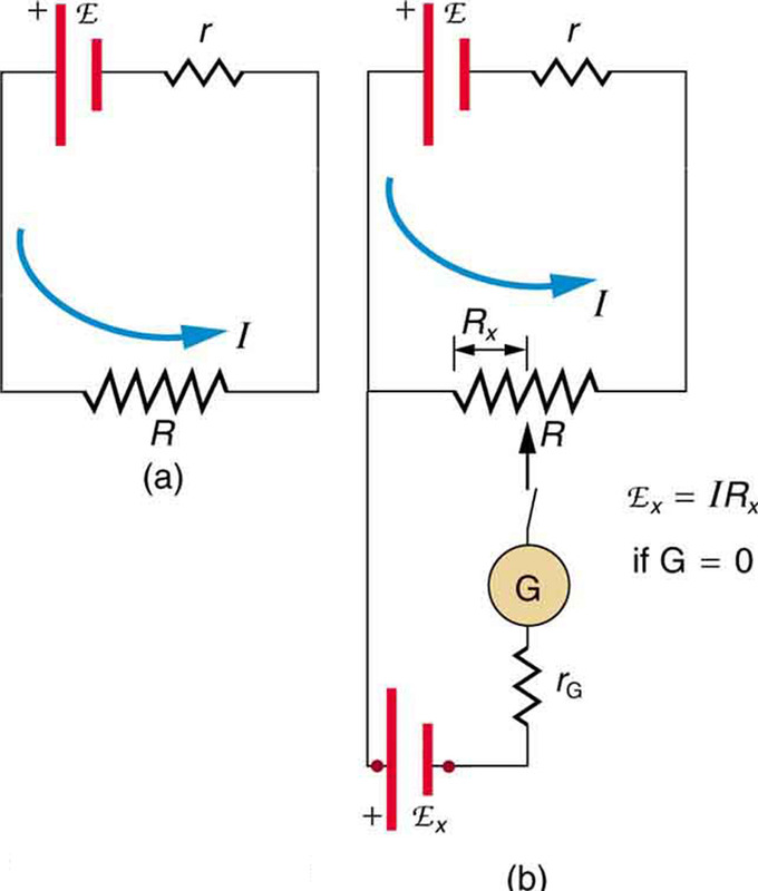
Potentiometer: The potentiometer is a nix measurement device. (a. ) A voltage source connected to a long wire resistor passes a constant electric current I through it. (b.) An unknown EMF (labeled script Ex) is connected as shown, and the betoken of contact along R is adjusted until the galvanometer reads nothing. The segment of wire has a resistance Rx and script Ex=IRx, where I is unaffected by the connection, since no current flows through the galvanometer. The unknown EMF is thus proportional to the resistance of the wire segment.
Standard EMF is substituted for emf10 , and the contact indicate is adapted until the galvanometer reads zero, and then that emfsouth=IRs. In both cases, no electric current passes through the galvanometer. The current I through the long wire is identical. Taking the ratio emften /emfsouth , I cancels, and solving for emfx gives what is seen in.
Considering a long uniform wire is used for R, the ratio of resistances Rx/Rs is the aforementioned equally the ratio of the lengths of wire that zero the galvanometer for each EMF. The three quantities on the right-hand side of the equation are at present known or measured, and emfx can be calculated. There is often less incertitude in this calculation than when using a voltmeter direct, but information technology is not nix. There is e'er some uncertainty in the ratio of resistances Rten/Rs and in the standard EMFs. Furthermore, information technology is not possible to tell when the galvanometer reads exactly zero, which introduces error into both Rx and Rs , and may also affect the current I.
Resistance Measurements
Many and so-chosen ohmmeters mensurate resistance. Most common ohmmeters apply a voltage to a resistance, measure the current, and calculate the resistance using Ohm 'south constabulary. Their readout is this calculated resistance. Simple configurations using standard voltmeters and ammeters have limited accuracy, because the meters change both the voltage applied to the resistor and the current flowing through it. The Wheatstone bridge is a null measurement device for calculating resistance by balancing potential drops in a circuit. The device is called a span because the galvanometer forms a bridge between two branches. A multifariousness of span devicesare used to make null measurements in circuits. Resistors R1 and R2 are precisely known, while the arrow through R3 indicates that information technology is a variable resistance. The value of Rthree can exist precisely read. With the unknown resistance Rx in the circuit, R3 is adapted until the galvanometer reads nada.
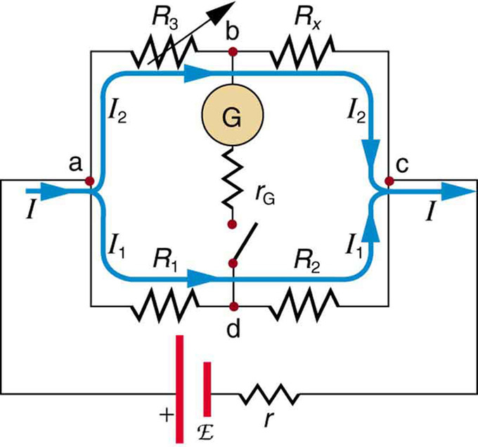
Wheatstone Bridge: The Wheatstone bridge is used to calculate unknown resistances. The variable resistance R3 is adapted until the galvanometer reads goose egg with the switch airtight. This simplifies the circuit, allowing Rx to exist calculated based on the IR drops.
The potential difference between points b and d is then zero, meaning that b and d are at the aforementioned potential. With no electric current running through the galvanometer, it has no consequence on the rest of the excursion. So the branches abc and adc are in parallel, and each co-operative has the full voltage of the source. Since b and d are at the same potential, the IR driblet along ad must equal the IR driblet along ab. Again, since b and d are at the same potential, the IR drop forth dc must equal the IR drop along bc. This equation is used to calculate the unknown resistance when current through the galvanometer is zero. This method can be very accurate, but it is express by two factors. First, it is not possible for the current through the galvanometer to exist exactly zero. 2nd, there are e'er uncertainties in R1, R2, and R3, which contribute to the uncertainty in Rten.
Source: https://courses.lumenlearning.com/boundless-physics/chapter/voltmeters-and-ammeters/
Post a Comment for "When a Voltmeter Reads Zero Are the Currents Equal?"